BA Series Insulated Bimoprhs
Piezoelectric Insulated Bending Actuators
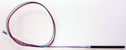
BA Series Bimorph
Specifications:
| Part Number | BA3502 | BA4010 | BA5010 | BA6020 |
|---|---|---|---|---|
| Dimensions | 35 x 2.5 mm | 40 x 10 mm | 50 x 10 mm | 60 x 20 mm |
| Thickness | 0.80 mm | 0.80 mm | 0.80 mm | 0.80 mm |
| Free Length | 28 mm | 33 mm | 43 mm | 53 mm |
| Deflection | 0.70 mm | 1.1 mm | 1.5 mm | 2.6 mm |
| Force | 0.08 N | 0.18 N | 0.3 N | 0.3 N |
| DC Voltage | +150 V | +150 V | +150 V | +150 V |
| AC Voltage | +/- 90 V | +/- 90 V | +/- 90 V | +/- 90 V |
| Cap. [1] | 20 nF | 100 nF | 125 nF | 300 nF |
| Stiffness | 220 N/m | 327 N/m | 400 N/m | 230 N/m |
| Reson Freq | 230 Hz | 250 Hz | 200 Hz | 60 Hz |
| Mass | 0.3 g | 1.7 g | 2.1 g | 5.0 g |
Specification Notes:
- Deflection: The peak-to-peak deflection of the tip when driven with the full voltage using the biased unipolar (three-wire) method. Slightly more deflection is possible with bipolar (AC, two-wire) drive method. This is also the recommended maximum deflection that the bender should experience. Lifetime will reduce if this is exceeded, and mechanical failure occur if the bender is deflected more than twice the recommended deflection.
- Blocked Force: The maximum force developed at the tip when restricted from moving, using the three-wire drive method. Or, the force required to reduce the deflection to zero when maximum voltage is applied. This is also the maximum recommend force the bender should be subjected to. At rest, with zero voltage applied, a force of this value will deflect the bender by Deflection/2.
- Dimensions: The total outside dimensions of the bender and electrodes
- Thickness: The bender thickness including protective coating
- Free Length: The recommended length that should be free to move after mounting
- Voltage: Maximum DC voltage applied using the biased unipolar (three-wire) drive method, see Electrical Connection. Equal to the maximum DC bias voltage.
- AC Voltage: Maximum amplitude of an AC voltage applied using the unipolar (two-wire) drive method, see Electrical Connection.
- Capacitance: Electrical capacitance of both sides in parallel. This value should be used for calculating the required current in the three-wire or parallel configuration. Tolerance is +/-30%
- Resonance Frequency: Resonance frequency of the first bending mode, using the recommended free-length mounting conditions and no load mass.
Features
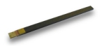
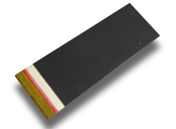
The BA family of bender actuators are piezoelectric bimorph actuators poled in the parallel configuration. An insulated resin coating is applied to the external surfaces to protect the actuator and to eliminate electrical faults. The actuators can be wired in a three-wire or two-wire configuration as illustrated below.
Electrical Connections
The recommended methods for driving the BA series benders are illustrated below. These recommendations apply to any parallel-poled two-layer bender actuator rated for 150V.
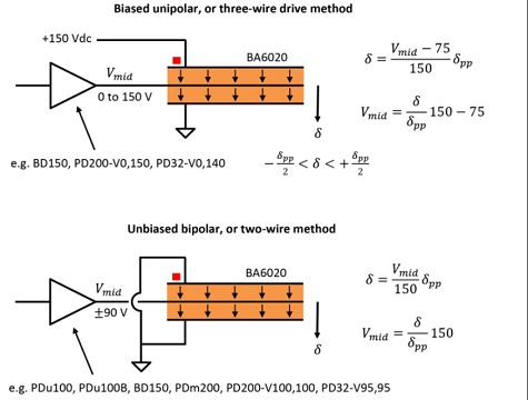
The three-wire method (biased unipolar drive method [1]) only requires positive voltages and results in positive electric field across both piezo layers. The maximum downward deflection δ=δpp/2 is achieved when Vmid=150 , and the maximum upward deflection δ=-δpp/2 is achieved when Vmid=0 . The advantage of this method is that only one supply polarity is required. The disadvantages include the constant DC electric field that can attract contamination and eventually create a path for leakage current, and the top electrode is connected to high voltage, which may not be optimal for safety in some applications. Suitable amplifier modules include the BD150 and MX200 (in 150V configuration). Fully enclosed amplifiers include the PD200-V0,150 for general purpose applications, or the PD32-V0,140 for up to 32 channels.
The two-wire method (bipolar drive method [1]) requires two supplies and results in both positive and negative electric fields across the piezo layers. The maximum deflection and force is slightly higher due to the larger voltage swing compared the biased unipolar method. The maximum downward deflection is achieved when Vmid=90 and the maximum upward deflection is achieved when Vmid=-90. The advantages include: both external electrodes can be grounded, and there there is zero elongation and electric field at rest. Some amplifiers such at the PDm200, PD200-V100,100, and PD32-V95,95 will naturally produce a +/-90V output; however, if the connection to ground is not required, a single-supply amplifier can also be used. The PDu100, PDu100B, and BD150 are designed for applications where the ground connection is not required.
The two-wire bipolar drive is recommended for most applications. To maximize lifetime, the maximum DC voltage can be limited to +/-75V, which provides the same deflection as the three-wire configuration with a +150V bias voltage. If the ground connection is not essential, the PDu100 and PDu100B are good starting choices for low-frequency applications, where noise is not a concern. Higher current and speed can be achieved with a BD150 or MX200 driver. Grounded external electrodes can be used with the PDm200, PD200-V100,100, or PD32-V95,95.
Wires can be attached using conductive epoxy (Circuitworks CW2400) or standard solder and Rosin flux. After flux application, a one second contact with a 300C iron is recommended. The positive terminal is indicated by a red stripe.
Mounting
Bimorph actuators can be mounted with a soft clamp or bonded to a base using an adhesive such as Araldite. The longest life time is achieved when soft materials such as rubber are used at the clamping surface. The recommended clamping length is 2mm for for the BA3502 and 5mm for other sizes.
Lifetime
The expected lifetime for a 10% failure rate is 500,000 cycles with full-range deflection. The load force and deflection must be kept within specifications.
Electrical Current Requirements
 Calculate Power Bandwidth
The required current is I=C dV/dt, where I is the current, C is the effective capacitance, and dV/dt is the voltage rate-of-change. For a sine-wave, the required peak current is equal to:
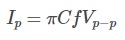
Where Vp-p is the peak-to-peak voltage. For a triangle wave, the required peak current is:
![]()
Options/OEM Customization
- Custom range and dimensions
- Custom wiring arrangement/connectors
RoHS and Reach Compliance
References
[1] A New Electrical Configuration for Improving the Range of Piezoelectric Bimorph Benders; S. A. Rios, A. J. Fleming; Sensors and Actuators A: Physical, 2015.