PD200 - 60W Voltage Amplifier
Piezoelectric Drivers
 PD200 Users Manual
 Calculate Power Bandwidth
Specifications:
| Electrical Specifications | |||
|---|---|---|---|
| Output Voltage Ranges | 100 Vp-p | 150 Vp-p | 200 Vp-p |
| RMS Current | 1.2 Amps | 0.91 Amps | 0.57 Amps |
| Pulse Current | 10.0 Amps | 10.0 Amps | 10.0 Amps |
| Power Bandwidth | 470 kHz | 310 kHz | 230 kHz |
| Gain | 20 V/V | ||
| Slew Rate | 150 V/us | ||
| Signal Bandwidth | 680 kHz | ||
| Max Power | 60 W Dissipation | ||
| Load | Any | ||
| Noise | 714 uV RMS (10 uF Load, 0.03 Hz to 1 MHz) | ||
| Protection | Continuous short-circuit, thermal | ||
| Voltage Monitor | 1/20 V/V (BNC) | ||
| Current Monitor | 1 V/A (BNC) | ||
| Analog Input | +/-10V (BNC, Zin = 27k) | ||
| Output Connectors | LEMO 00, LEMO 0B, Screw Terminals, BNC | ||
| Power Supply | 90 Vac to 250 Vac | ||
| Mechanical Specifications | |||
|---|---|---|---|
| Environment | 0 - 40 C (32-104 F), Non-condensing humidity | ||
| Dimensions | 275 x 141 x 64 mm (10.8 x5.5 x 2.5 in) | ||
| Weight | 1kg (2.2 lb) | ||
Features
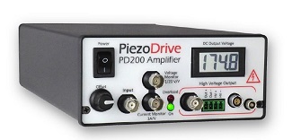
The PD200 is a wide bandwidth, low noise linear amplifier for driving piezoelectric actuators and other loads. The output voltage range can be unipolar, bipolar, or asymmetric from 50V to 200V. Up to +/-200V can be achieved in the bridged configuration. The PD200 can drive any load impedance including unlimited capacitive loads such as stack actuators; standard piezoelectric actuators; two wire benders; and three-wire piezoelectric benders requiring a bias voltage.
Configuration options include the voltage range, polarity, and output current. The voltage range can also be limited by two user-accessible potentiometers. The PD200 is suited to a wide range of applications including electro-optics, ultrasound, vibration control, nanopositioning systems, and piezoelectric motors.
There are four output connectors including Lemo 00, Lemo 0B, BNC, and screw terminals that allow the direct connection to almost any commercially available piezoelectric actuator. A rear-panel connector also provides a temperature output, overload monitor, and external shutdown input.
| Compatible Actuators | |||
|---|---|---|---|
| Stack Actuators | 50V to 200V | ||
| Plates and Tubes | up to +/-100V | ||
| Two Wire Benders | up to +/-100V | ||
| Three Wire Benders | 0 to 200V with 200V bias | ||
| Three Wire Benders | +/-100V with +/-100V bias | ||
Output Voltage Range
The desired output voltage range is specified when ordering. The default output range is 0V to +200V (PD200-V0,200). The available voltage ranges and associated current limits are listed below. Fine adjustments to the voltage range can also be made, see “Voltage Limits” below.
| Voltage Range | RMS Current | Peak Current | Order Code |
|---|---|---|---|
| 0 to +200 | 0.57A | 2A | PD200-V0,200 |
| 0 to +150 | 0.91A | 2A | PD200-V0,150 |
| 0 to +100 | 1.20A | 2A | PD200-V0,100 |
| 0 to +50 | 1.20A | 2A | PD200-V0,50 |
| -50 to +150 | 0.57A | 2A | PD200-V50,150 |
| -50 to +100 | 0.91A | 2A | PD200-V50,100 |
| -50 to +50 | 1.20A | 2A | PD200-V50,50 |
| -100 to +100 | 0.57A | 2A | PD200-V100,100 |
| -100 to +50 | 0.91A | 2A | PD200-V100,50 |
Output Current
The PD200 has a peak and average current limit as described in Table 1. The RMS current limit defines the maximum frequency that is achievable with a capacitive load. This topic is discussed in “Power Bandwidth”.
During short-circuit the output current is limited to the rated maximum. The peak current can be drawn for up to five milliseconds before the output is disabled for three seconds. The average current limit has a time-constant of 30 milliseconds and is reset 100 milliseconds after a previous current pulse. This behaviour is described in “Overload and Shutdown”.
Voltage Limits
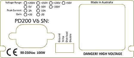
The output voltage range can be restricted to an arbitrary positive and negative value using two potentiometers accessed from a pair of holes on the bottom panel. By gently turning the potentiometers clockwise with a 2-mm flat-head screwdriver, the full voltage range becomes available. The voltage range is reduced by turning the potentiometers anti-clockwise. The hole closest to the front panel controls the negative voltage range while the rear hole controls the positive range.
Pulse Current Option
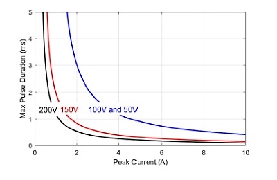
For applications that require a high peak current, the peak current limit can be increased to 10 Amps by appending the order code with “-PULSE”, e.g. “PD200-V0,200-PULSE”. In this configuration, the average current limit remains the same; however, the peak current limit is increased to 8 Amps and the maximum pulse duration is reduced to the time listed in Table 2. The voltage span is the peak-to-peak output voltage range, e.g. the voltage span for the -50V to +150V range is 200V.
| Voltage Span | Pulse Current | Pulse Time |
|---|---|---|
| 200V | 10A | 100 us |
| 150V | 10A | 150 us |
| 100V | 10A | 400 us |
| 50V | 10A | 400 us |
For a current pulse that is less than the peak current limit, the maximum pulse duration is described in Figure 1.
Power Bandwidth
The online power bandwidth calculator estimates the highest achievable frequency with a capacitive load impedance. The calculator considers the current limit, slew-rate, output impedance, and small-signal bandwidth.
Calculate Power Bandwidth
With a capacitive load, the RMS current for a sine-wave is 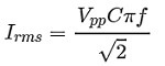
where Vpp is the peak-to-peak output voltage, C is the load capacitance and f is the frequency. Therefore, the maximum frequency for a given RMS current limit Irms, capacitance, and voltage is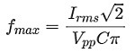 . The above equation is also true for any periodic waveform, including triangle waves and square waves. This property arises since the amplifier detects average current, which is not affected by the waveform shape.
The ‘power bandwidth’ is the maximum frequency at full output voltage. When the amplifier output is open-circuit, the power bandwidth is limited by the slew-rate; however, with a capacitive load, the maximum frequency is limited by the RMS current and load capacitance. The power bandwidth for a range of capacitive loads is listed below.
| Load Capacitance | 50V Range | 100V Range | 150V Range | 200V Range |
|---|---|---|---|---|
| No Load | 520 kHz* | 470 kHz* | 310 kHz* | 230 kHz* |
| 10 nf | 520 kHz* | 470 kHz* | 270 kHz | 130 kHz |
| 30 nf | 370 kHz | 180 kHz | 91 kHz | 43 kHz |
| 100 nf | 110 kHz | 56 kHz | 27 kHz | 13 kHz |
| 300nf | 37 kHz | 18 kHz | 9.1 kHz | 4.3 kHz |
| 1uf | 11 kHz | 5.6 kHz | 2.7 kHz | 1.3 kHz |
| 3uf | 3.7 kHz | 1.8 kHz | 910 Hz | 430 kHz |
| 10uf | 1.1 kHz | 560 Hz | 270 Hz | 130 Hz |
In the above table, the frequencies limited by slew-rate are marked with an asterisk. The slew-rate is approximately 150 V/uS which implies a maximum frequency of 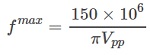
Small Signal Bandwidth
The small-signal -3 dB bandwidth is listed in the Table 4
| Load Cap | Bandwidth |
|---|---|
| No Load | 684 kHz |
| 10 nf | 759 kHz |
| 30 nf | 720 kHz |
| 100 nf | 388 kHz |
| 300 nf | 172 kHz |
| 1 uf | 60 kHz |
| 3 uf | 21 kHz |
| 10 uf | 6.4 kHz |
| 30 uf | 2.4 kHz |
| 110 uf | 940 Hz |
Noise
The output voltage noise contains a low frequency component (0.03 Hz to 20 Hz) that is independent of the load capacitance; and a high frequency (20 Hz to 1 MHz) component that is approximately inversely proportional to the load capacitance.
The noise is measured with an SR560 low-noise amplifier (Gain = 1000), oscilloscope, and Agilent 34461A Voltmeter. The low-frequency noise is plotted in Figure 4. The RMS value is 650 uV with a peak-to-peak voltage of 4.3 mV.
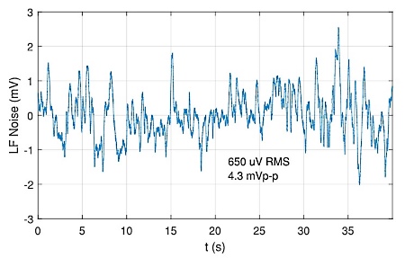
The high frequency noise (20 Hz to 1 MHz) is listed in the table below versus load capacitance. The total RMS noise from 0.03 Hz to 1 MHz is found by summing the RMS values, that is 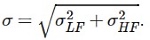
| Load Cap. | Bandwidth | HF Noise (RMS) | Total Noise (RMS) |
|---|---|---|---|
| No Load | 684 kHz | 1.60 mV | 1.72 mV |
| 10 nf | 759 kHz | 1.65 mV | 1.77 mV |
| 30 nF | 720 kHz | 1.75 mV | 1.86 mV |
| 100 nF | 388 kHz | 2.08 mV | 2.17 mV |
| 300 nF | 172 kHz | 2.18 mV | 2.27 mV |
| 1 uF | 60 kHz | 998 uV | 1.19 mV |
| 3 uF | 21 kHz | 414 uV | 771 uV |
| 10 uF | 6.4 kHz | 295 uV | 714 uV |
| 30 uF | 2.4 kHz | 280 uV | 708 uV |
| 110 uF | 940 Hz | 264 uV | 702 uV |
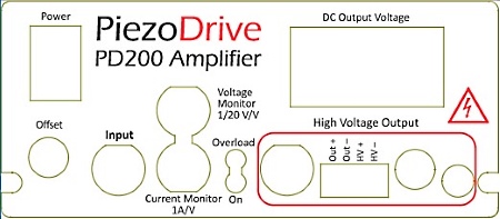
Front Panel
| Control | Type | Function |
|---|---|---|
| Power | Power On/Off | |
| Offset | Adds a DC offset to the input signal | |
| Input | Input | Input signal ( +/-15V max) |
| Voltage Monitor | Output | The measured output voltage, scaled by 1/20 |
| Current Monitor | Output | The measured output current, 1 A/V |
| Overload | RED when the amplifier is disabled or in an overload state | |
| Power | GREEN when the power is on | |
| HV- | Output | Connected to the negative high-voltage power supply rail |
| HV+ | Output | Connected to the positive high-voltage power supply rail |
| Output- | Output | High-voltage output signal return (used to measure current) |
| Output+ | Output | High-voltage output signal |
| LEMO 00 Output | Output | High-voltage output connector, suits LEMO FFA.00.250 cable plug |
| LEMO 0B Output | Output | High-voltage output connector, suits LEMO FGG.0B.302 cable plug |
| DC Output Volt. | Display showing average output voltage |
The front panel connectors and recommended mating plugs are listed below.
| Connector | Mating Connector | Manufacturer | PCB Component |
| BNC | Any BNC | ||
| 4-Way Screw Term. | TJ0431530000G | Amphenol | OQ0432510000G |
| LEMO 00 | FFA.00.250 | LEMO | EPL.00.250 |
| LEMO 0B | FGG.0B.302 | LEMO | EPG.0B.302 |
The LEMO 0B connector is recommended for applications requiring more than 1 Amp RMS output current. Preassembled LEMO cable assemblies are available by request.
Rear Panel
| Control | Type | Function |
|---|---|---|
| Ground | Ground/Earth | |
| Temp | Output | Internal heatsink temperature, 0.1 V/degree (Celsius) |
| Overload | Output | +5V output when the amplifier is disabled or in overload state |
| Disable | Input | A voltage from +3V to +24V disables the amplifier |
The rear panel connector and recommended mating plug is listed below.
| Connector | Mating Connector | Manufacturer | PCB Component |
| 4-Way Screw Term. | TJ0631530000G | Amphenol | OQ0432510000G |
Amplifier Configuration
The amplifier can be configured with an inverting, or non-inverting gain of 20. Custom gain configurations are available on request.
| Amplifier Configuration | Order Code | Notes |
|---|---|---|
| Non-inverting | (default) | |
| Inverting | -INV |
The DC offset control is configurable with a positive or bipolar range. The maximum achievable DC offset is limited by the output voltage range of the amplifier. In general, the positive DC offset range is recommended as this allows direct selection of zero offset; however, the bipolar range may be preferable for amplifiers configured with a negative output range.
The front panel potentiometer can be disabled by enabling a PCB mounted trim-pot. The PCB trim-pot can be set to a required fixed value prior to shipping.
| Offset Configuration | Order Code | Notes |
|---|---|---|
| Positive Offset Range | Zero to positive full range (default) | |
| Bipolar Offset Range | -OR2 | Negative to positive full range |
| Front panel source | (default) | |
| PCB trim-pot source | -OS2 | Disables front panel adjustment |
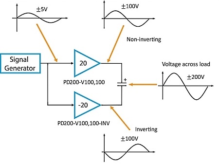
Bridged Mode
In bridged mode, two amplifiers are connected in series to double the output voltage range and power.
For example, Figure 5 shows the configuration to obtain +/-200V across the load. A +/-5V signal applied to both inputs produces +/-200V across the load. In bridged mode, only the Output+ terminal from each amplifier is used, the negative output terminal is not connected. Since there is no current returning through the negative terminal, the current monitor is disabled; however, the overload and protection features are unaffected. Common bridged-mode configurations are listed in Table 8.
| Load Voltage | RMS Current | Positive Amp | Negative Amp |
| +/-200V | 0.57 A | PD200-V100,100 | PD200-V100,100-INV |
| +/-100V | 1.2 A | PD200-V50,50 | PD200-V50,50-INV |
Overload Protection
The amplifier is protected against short-circuit, over-current, and excessive temperature. During these conditions, the front panel overload indicator will illuminate and the rear-panel Overload signal is +5V.
During an overload or shutdown state, the output is disabled.
When the amplifier is switched on, the overload protection circuit is engaged by default and clears after three seconds.
The amplifier can be shut down by an external source by applying a voltage of between +3V and +24V to the Shutdown input on the rear panel. The impedance of the shutdown input is approximately 5 kΩ.
Enclosure
The enclosure has a side air intake and rear exhaust, which cannot be obstructed. If sufficient airflow is not available, the amplifier will enter a thermal overload state as discussed in “Overload and Shutdown”.
Three PD200 amplifiers can also be supplied in 2U x 19 inch rack mountable enclosure. The order code is PD200-3ChRack-X, where X is the standard order configuration options. For example, PD200-3ChRack-V0,200 is a 19 inch rack enclosure with three PD200 amplifiers with an output voltage range of 0V to 200V. Multple configuration options can be specified by listing the configurations sequentially, these will be installed from left to right in the rack enclosure.
Standard Delivery Contents
- PD200 amplifier in chosen voltage configuration
- Two 4-way plug-in screw terminals installed (Amphenol TJ0431530000G)
- IEC C13 main power cable, suited to the shipping destination
Warranty
PiezoDrive amplifiers are guaranteed for a period of 3 months. The warranty does not cover damage due to misuse or incorrect user configuration of the amplifier.
Previous Versions
| Hardware Version | Manufactured | Manual |
|---|---|---|
| V1 | 2014-2017 | Download User Manual |