SCL Series Closed Loop Stack Actuators
150V Piezoelectric Stack Actuators with Strain Gage for closed loop operation
![]() SCL Series Closed-Loop Stack Actuators
SCL Series Closed-Loop Stack Actuators
General Specifications:
| Drive Voltage | -30V to +150V |
|---|---|
| Stroke Tolerance | +/- 15% |
| Length Tolerance | +/- 0.1 mm |
| Hysteresis | <15% |
| Operating Temperature | 0 to +70 Celsius |
| Operating Humidity | <40% recommended |
| Storage Temperature | -25 to +80 Celsius |
| Storage Humidity | <40% Recommended |
| Strain Gauge | Full Bridge, 350 Ohm |
| Gauge Factor | 2 |
| Bridge Voltage | <5 Vrms |
Part numbers:
| Ord. Code | Disp 150V | Disp -30 to 150V | Lgth | X Sect |
Cap. +/- 20% | Mass | Blk Frc | Stiff | Res Freq |
|---|---|---|---|---|---|---|---|---|---|
| um | um | mm | mm | uF | g | N | N/um | kHz | |
| SCL050509 | 9.5 | 12 | 9 | 5x5 | 0.75 | 2.0 | 1000 | 105 | 140 |
| SCL050518 | 20 | 26 | 18* | 5x5 | 1.6 | 3.8 | 1000 | 50 | 70 |
| SCL050536 | 41 | 53 | 36 | 5x5 | 3.5 | 7.4 | 1000 | 24 | 34 |
| SCL070718 | 19 | 24 | 18* | 7X7 | 3.0 | 7.3 | 1900 | 100 | 70 |
| SCL070736 | 38 | 50 | 36 | 7x7 | 6.0 | 14 | 1900 | 50 | 35 |
NOTES:
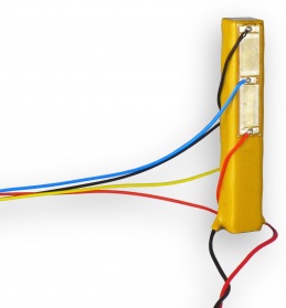
* The strain gauge electrical contacts on the 18mm actuators are close to the end of the stack and may contact the mounting surface. An example of an 18mm length actuator is pictured in Section 4. To avoid short-circuit of the strain gauge, ball ends are recommended. Alternatively, a 0.4mm ceramic spacer can be added to both ends by appending the order code with -Spacer, e.g. SCL050518-Spacer
Features
The SCL family of stack actuators include a full-bridge strain sensor for closed-loop control and strain monitoring. The stack actuator is ceramic encapsulated for humidity protection and epoxy coated to insulate the high-voltage wiring and provide mechanical protection. The SCL actuators are ideally matched to the PDu150CL driver that can be pre-calibrated to an actuator when ordered together. Applications include: Nanopositioning, Microscopy, Precision Machining, Vibration Control, Hydraulic Pumps, Valves, and Optics.
Mounting
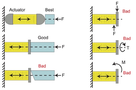
Stack actuators should not be exposed to significant tensile loads, unequally distributed loads, off-axis loads, bending moments, or torque. To reduce mounting errors, a ceramic or stainless steel ball end can be used to interface the stack actuator to the load. Flexural mechanisms are also recommended.
Suitable adhesives for low temperature operation include cyanoacrylate, e.g. superglue gel, and general-purpose two-part epoxies, e.g. Loctite 3430. In applications where heat dissipation or operation at elevated temperature is required, Loctite 9466 is recommended.
The maximum recommended tensile load is 10% of the blocking force. In applications that require bi-directional forces or high-speed motion, a preload force is recommended with a magnitude greater than the maximum tensile load. This guarantees that the actuator is always in compression. The maximum recommended preload is 50% of the blocking force.
Strain Gage
The strain gauge is a 350-Ohm full-bridge arrangement constructed from two 90 degree rosettes. The strain elements aligned with the direction of the piezo expansion are labelled +ε and the 90 degree elements are denoted –νε. This convention is adopted since a positive strain +ε causes a negative resistance change in the 90 degree element due to Poisson’s ratio (ν).
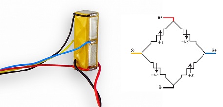
The induced differential voltage VS for a two-varying element full bridge is [1, 2]
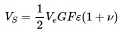
Where Ve is the excitation voltage (e.g. 5V), GF is the gauge factor (e.g. 2), ε is the strain, and ν is the Poisson’s ratio (0.34 for PZT5H). For a full-scale strain of 0.1%, the expected bridge voltage is 6.7 mV. The PDu150CL amplifier module has an input referred noise of 3 uVrms from 0.1 Hz to 100 Hz. Therefore, the predicted standard deviation of the strain measurement noise is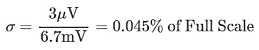
That is, the 6σ-resolution [1] is 0.26% of full scale for a 100-Hz bandwidth. For example, the closed-loop resolution of the SCL050509 and PDu150CL amplifier module is approximately 25nm (peak-to-peak) with a 100-Hz bandwidth.
Recommended Driver
The PDu150CL driver module (version 5 or above) provides all of the required functions for open- or closed-loop operation. The connection diagram is illustrated below.
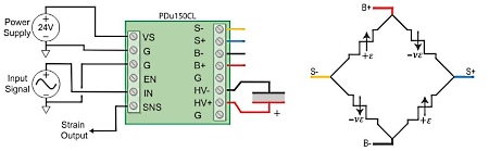
After connection, the module is calibrated so that a full-range extension of the actuator produces a +10V sensor output. The module can then be switched to closed-loop where a 0V to 10V input produces a zero to the full-range extension of the actuator.
When an actuator and PDu150CL driver are ordered together, factory calibration can be requested. By default, the strain gauge is calibrated so that a 0V to +150V actuator voltage produces a 0V to +10V sensor signal. In closed-loop, the full stroke is produced by a +10V input signal, however, the maximum recommended input in closed-loop is 9V. This leaves some ‘head-room’ for the controller to compensate for reduced actuator stroke, due to, for example, reduced temperature or actuator ageing. The actuator is calibrated in an unmounted state so the calibration should be checked after mounting, and adjusted if necessary.
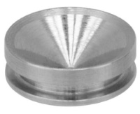
Ball Ends
SCL stack actuators can be supplied with ball ends to improve the load distribution and reduce bending during service. One or two ball ends can be specified by adding one of the following suffixes to the order code: -TBE (Top Ball End), -BBE (Bottom Ball End), or -2BE (Both Ball Ends). E.g. SCL050509-2BE.
| Actuator Cross Section | Hemishpere Diameter | Additional Length |
|---|---|---|
| 5x5 mm | 5 mm | 2.5 mm per ball end |
| 7x7 mm | 7 mm | 3.5 mm per ball end |
Mounting cups are available for 5mm and 7mm hemispheres.
| Order Code | Suits Hemishpere | Outside Diameter | Additional Length |
|---|---|---|---|
| SCUP5 | 5 mm | 5 mm | 0.56 mm per cup |
| SCUP7 | 7 mm | 7 mm | 0.78 mm per cup |
Stroke
When a stack actuator drives a stiff spring, the range is reduced by the factor where kp is the actuator stiffness and kL is the load stiffness.
The stroke can also be reduced by restraining the end plates, e.g. by bonding the actuator to a stiff base. This effect is most significant in actuators with a length less than twice the width.
Capacitance
The actuator capacitance is the small-signal capacitance measured at room temperature. Due to hysteresis, the effective capacitance increases with applied voltage. When operating at full range, the effective capacitance is approximately 1.5 times the small-signal capacitance. The capacitance also increases with temperature. A temperature increase of approximately 50 degrees C will double the effective capacitance.
Thermal
Temperature rise during operation is due to resistive heating in the metal layers, mechanical friction, and energy lost due to hysteresis. The generated heat is dissipated by surface convection and conduction through the end plates.
Due to thermal conduction, flat end plates are recommended when the operating frequency is continuously beyond approximately 500 Hz. Actuators with a larger cross-sectional area provide better thermal conduction; however, these also require a higher drive current.
The SCL series actuators can be operated at temperatures up to 70 degrees Celsius. Versions with a higher temperature range are available on request.
The actual temperature rise during operation depends on a number of factors, including the thermal impedance of the connected structure, the air-flow over the actuator, and the magnitude and wave-form of the driving signal. As an indication of temperature rise, the table below lists the approximate frequency where the temperature of an SCL actuator is increased by 25 degrees when driven by a 150 Vp-p sine wave.
| Actuator Cross Section | 10 Degrees C Rise | 25 Degrees C Rise |
|---|---|---|
| 5x5 mm | 600 Hz | 1.5 kHz |
| 7x7 mm | 500 Hz | 3 kHz |
The above figures assume that the operating frequency is below the first resonance frequency of the actuator and connected structure. Significantly more heat can be produced near a resonance frequency.
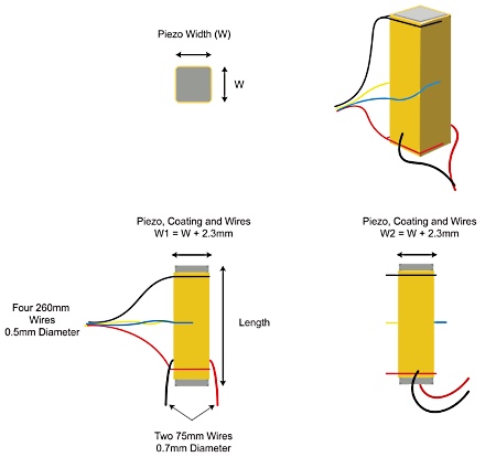
Dimensions
The total stack dimensions are based on the width and length of the ceramic listed in the specifications. The total width dimensions, including the wires and strain gauge, is 2.3mm wider than the ceramic.
References