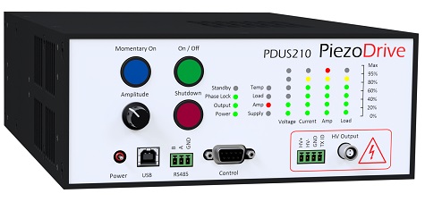
PDUS210 - 210 Watt Ultrasonic Driver
Piezoelectric Drivers
 PDUS210 Manual-V5
Introduction to Ultrasonic Drivers
Download Desktop Software, Version: 500015
Download Firmware, Version: 500021
Download 3D Model
Download External Transformer 3D Model
Features
The PDUS210 is a complete solution for driving and analysing ultrasonic actuators up to 210 Watts. Functions include high-speed resonance tracking of both series and parallel resonance modes, vibration amplitude control, pulsed excitation, frequency modulation, and analysis functions such as impedance and frequency response measurement. The PDUS210 is well suited to both OEM product integration and laboratory use for research and development. Applications include ultrasonic drilling and cutting, cleaning, medical devices, dental devices, ultrasonic testing, cavitation, and vaporization.
The PDUS210 can be controlled from multiple sources including a PC and the included software package, front panel controls, and/or external logic signals from a foot switch for example. An API for external controllers is also available for RS485 and USB connections, which are suitable for automatic test applications and embedded industrial machinery.
The PDUS210 generates a pure sine-wave output which is ideal for operating at the electrical parallel resonance, or ‘anti-resonance’. This operating point is close to the mechanical resonance frequency but is less sensitive to changes in load dissipation, which is useful in precision machining applications where constant vibration amplitude is desired. Current and power control are also available for regulating vibration amplitude at the series resonance mode.
The PDUS210 is available with standard output voltage ranges from 17 Vrms to 282 Vrms, and current ranges from 0.7 Arms to 11 Arms. These ranges are optimized for load impedances ranging from 1.5 Ohms to 400 Ohms at resonance. For research and development applications, a reconfigurable version is available (PDUS210-FLEX), this version uses external output matching transformers to allow operation at any of the available output voltage ranges.
Ultrasonic Drive Methods
For an introduction to driving ultrasonic transducers, refer to Introduction to Ultrasonic Drivers
Specifications
| Electrical Specifications | ||
|---|---|---|
| Specification | Value | Notes |
| Output Voltage | 0 - 800 Vp-p | See standard voltage ranges |
| Output Current Max | 0 - 32 Ap-p | See standard voltage ranges |
| Load Impedance | 1 Ohm - 5 kOhm | See standard voltage ranges |
| Output Waveform | Sine wave | |
| DC Output Voltage | Zero | See Manual for other options |
| Output Isolation | Isolated | Grounded also possible |
| Max Output Power | 210W | With optimal load impedance |
| Internal Power Dissapation | 130W | Maximum |
| Frequency Range | See Table Below | 6 kHz to 500 kHz with modification |
| Power Supply | 48V, 280Watt | |
| Control Setpoints | Phase, current, power | 1ms frequency update rate |
| Pulse Generation | Series or parallel resonance | |
| Interface | USB and RS485 | |
| Digital IO | 4 DIO | For manual control inputs |
Standard Output Voltage Range
The following table lists the specifications of each model variant, including: the maximum output voltage, the maximum output current, optimal load impedance and the recommended frequency range. Refer to the manual for unipolar output voltage options.
| Order Code | Max Volt
Vpk-pk
| Max Volt
VRMS
| Max Curr
Amps pk-pk
| Max Curr
Amps RMS
| Optimal Load Ohms | Load Range Ohms* | Freq.
kHz
|
|---|---|---|---|---|---|---|---|
| PDUS210-800 | 800 | 282 | 2 | 0.71 | 400 | 260-840 | 20-200 |
| PDUS210-600 | 600 | 212 | 2.6 | 0.92 | 225 | 146-472 | 20-200 |
| PDUS210-400 | 400 | 141 | 4 | 1.4 | 100 | 65-210 | 20-200 |
| PDUS210-200 | 200 | 70 | 8 | 2.8 | 25 | 16-52 | 20-200 |
| PDUS210-100 | 100 | 35 | 16 | 5.7 | 6.25 | 4-13 | 20-200 |
| PDUS210-50 | 50 | 17 | 32 | 11.3 | 1.56 | 1-3 | 20-200 |
Note: The output voltage resolution and tolerance is 8 bits, or 256 levels. Therefore, the smallest possible change in voltage is full-scale range / 256. The minimum output voltage is also limited by resolution. When the amplifier is enabled and the output voltage is set to zero volts, the actual output voltage may be up to 1% of the full-scale range.
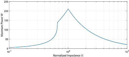
*The load impedance range is the range of impedances which guarantee more than 100W of power supplied to the load. Higher or lower impedances can be driven but with reduced power. The relationship between maximum achievable power and the load impedance is plotted in the following figure. In this plot, the impedance is normalized by the optimal impedance; that is,
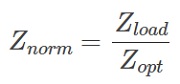
For example, the optimal impedance of the PDUS210-400 is 100 Ohms, so with a 50 Ohm load, the normalized impedance is 0.5, From the plot, it can be observed that greater than 100 W can be achieved with a normalized impedance from 0.65 to 2.1, which for the PDUS210-400, is 65 Ohms to 210 Ohms.
The impedance ranges for other common power levels are listed in the following table. For example, all amplifiers will supply more than 150W with a normalized load impedance between 0.71 and 1.4. For the PDUS210-400, this is equivalent to 71 Ohms and 140 Ohms.
| Minimum Power | Z Low | Z High |
|---|---|---|
| 150 W | 0.71 x Zopt | 1.4 x Zopt |
| 100 W | 0.65 x Zopt | 2.1 x Zopt |
| 50 W | 0.53 x Zopt | 4.2 x Zopt |
Mechanical Specifications
| Specification | Value | Notes |
|---|---|---|
| Enclosure Dimensions | 304.8 x 212 x 88 mm (12 x 8.35 x 3.46 In) | L x W x H |
| Mass | 2 kg (4.4 lb) | |
| Temperature Range | 0C - 50C (32 - 122F) | |
| Humidity | Non-condensing |
PDUS210-FLEX Specifications
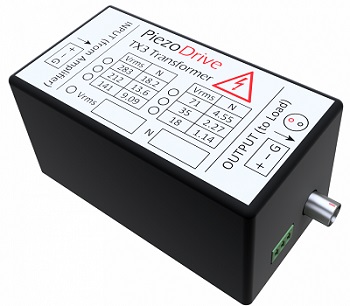
The PDUS210-FLEX is identical to the standard PDUS210 except that it requires an external transformer connected between the amplifier and transducer using the supplied cable. This allows the user to switch between different output voltage ranges by changing the external transformer. Please refer to the manual for unipolar output voltage options and operating instructions.
The PDUS210-FLEX must be purchased with at least one external transformer. The available part numbers and specifications are:
| Order Code | Turns Ratio | Volt pk-pk | Volt RMS | AMPS pk-pk | Amps RMS | Optimal Load Ohms | Load Range Ohms* | Freq kHz |
|---|---|---|---|---|---|---|---|---|
| TX210-800 | 18.18 | 800 | 282 | 2 | 0.71 | 400 | 260-840 | 20-200 |
| TX210-600 | 13.64 | 600 | 212 | 2.6 | 0.92 | 225 | 146-472 | 20-200 |
| TX210-400 | 9.09 | 400 | 141 | 4 | 1.4 | 100 | 65-210 | 20-200 |
| TX210-200 | 4.55 | 200 | 70 | 8 | 2.8 | 25 | 16-52 | 20-200 |
| TX210-100 | 2.27 | 100 | 35 | 16 | 5.7 | 6.25 | 4-13 | 20-200 |
| TX210-50 | 1.14 | 50 | 17 | 32 | 11.3 | 1.56 | 1-3 | 20-200 |
A kit containing five transformers ranging from 35Vrms to 282Vrms is also available (TX210-Kit1). This includes the following output voltage ranges: 35, 70, 141, 212, and 282 Vrms.
| Specification | Value | Notes |
| Input Connector | Plug-in screw Terminal | Connectin cable supplied |
| Output Connectors | Identical to PDUS210 | See "Front Panel" Section |
| Transformer Dimensions | 104 x 57 x 51 mm | L x W x H |
| Mass | 0.2 kg |
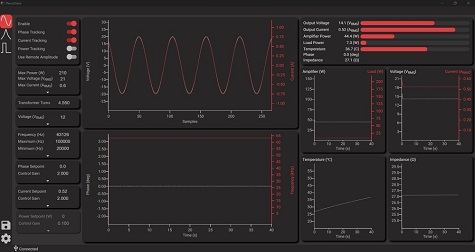
Desktop Software
The desktop application controls the amplifier and plots the key signals and operating conditions, which can be logged and exported as CSV files. The desktop application also includes advanced analysis functions such as impedance frequency response analysis, and a setup assistant to help new users analyze and choose operating conditions. Please refer to the manual for a full description.
Standard Delivery Contents
- PDUS210 Amplifier (in chosen configuration)
- IEC Power cable suited to the destination shipping address
- USB Cable (Type A to Type B)
- 4 Way plug-in screw terminals for output (Amphenol TJ0331530000G)
- 3 Way plug-in screw terminal for RS-485 connector (Amphenol TJ0431530000G)
Legacy Product Version 4
PDUS210 Manual
Download Desktop Software, Version: 300007
Download Firmware, Version: 300011
Download 3D Model
Quick Start Guide Video
Certifications
Warranty and Service
The PDUS210 is guaranteed against manufacturing defects for 12 months from the date of purchase. Contact Micromechatronics, Inc for service. Please include the amplifier serial number.