SR Ring Stack Actuators
150V Piezoelectric Ring Stack Actuators
 Calculate Power Bandwidth
Specifications:
| Part Number | SR080410 | SR080418 | SR120610 | SR120620 |
|---|---|---|---|---|
| Range +/- 10% | 14 um | 28 um | 14 um | 30 um |
| Length | 10 mm | 18 mm | 10 mm | 20 mm |
| OD | 8 mm | 8 mm | 12 mm | 12 mm |
| ID | 4.5 mm | 4.5 mm | 6 mm | 6 mm |
| Cap. +/- 20% | 0.8 uF | 1.6 uF | 2.4 uF | 5.0 uF |
| Blocking Force | 1300N | 1300N | 3000N | 3000N |
| Stiffness | 130 N/um | 65 N/um | 220 N/um | 100 N/um |
| Res. Freq. | 150 kHz | 83 kHz | 150 kHz | 75 kHz |
| Mass | 3.0 g | 5.0 g | 6.7 g | 12.9 g |
Features
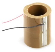
The SR family of ring stack actuators are high performance multilayer actuators with a vacuum compatible polymer coating and a large central aperture. The SR rings stacks are perfectly matched to the range of PiezoDrive amplifiers and driver modules. Applications include: Optics, Microscopy, Nanopositioning, and Precision machining.
Mounting
Stack actuators should not be exposed to significant tensile loads, unequally distributed loads, off-axis loads, bending moments, or torque.
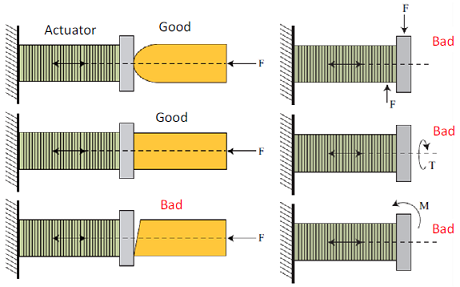
The maximum recommended tensile load is 10% of the blocking force. In applications that require bi-directional forces or high speed motion, a preload force is recommended with a magnitude greater than the maximum tensile load. This gaurantees that the actuator is always in compression. The maximum recommended preload is 50% of the blocking force.
Range
The range is specified for an applied voltage of -30V to +150V. If the input voltage is unipolar (0V to +150V) the specified range is reduced by a factor of 0.75. When a stack actuator is driving a stiff spring, the range is reduced by the factor

where kp is the actuator stiffness and kL is the load stiffness.
The travel range can also be reduced by restraining the end plates, e.g. by bonding the actuator to a stiff base. This effect is most significant in actuators with a length less than twice the outside diameter.
Capacitance
The actuator capacitance is the small-signal capacitance measured at room temperature. Due to hysteresis, the effective capacitance increases with applied voltage. When operating at full range, the effective capacitance is approximately twice the small-signal capacitance. The capacitance also increases with temperature. A temperature increase of approximately 50 degrees C will double the effective capacitance.
Thermal
Piezoelectric actuators dissipate heat when driven at full range with a high frequency. PiezoDrive actuators can be operated continuously at temperatures up to 85 degrees C. Continuous operation beyond this temperature may damage the actuator.
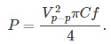
The dissipated heat is approximately 10% of the applied electrical power. For a sine-wave, the applied electrical power is:
Electrical Current Requirements
Calculate Power Bandwidth
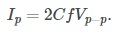
The required current is I=C dV/dt where I is the current, C is the effective capacitance, and dV/dt is the voltage rate of change. For a sine-wave, the required peak current is equal to:
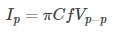
where Vp-p is the peak-to-peak voltage. For a triangle wave, the required peak current is equal to:
Recommended Drivers
| Amplifier | Application |
|---|---|
| PDm200B | General purpose, low cost |
| MX200 | High Current, Low noise, low cost |
| PDu150 | Ultra-low noise |
| PD200 | High speed, low noise |
| PX200 | High current, low noise |
Connecting Wires
All of the connecting wires are 100mm AWG26 PTFE insulated wires. Other lengths are available on request. Red identifies the positive terminal.
Vacuum Compatibility
The SR Actuators are supplied with a vacuum compatible UV cured lacquer coating which meets the outgassing requirements for NASA SP-R-0022A.
Options / OEM Customization
- Custom range and dimensions
- Custom wiring arrangement/connectors
- Preload or mechanical amplifier mechanisms
Piezoelectric Properties
The piezoelectric material is similar to PZT-5H and Navy Type VI.
| Property | Symbol | Value | Unit |
|---|---|---|---|
| Piezoelectric constants | d33 | 600 | 10-12m/V |
| d31 | -270 | 10-12m/V | |
| g33 | 19.4 | 10-3Vm/N | |
| g31 | -9.2 | 10-3Vm/N | |
|
Electro-mechanical coupling coefficients |
Kp | 0.65 | NA |
| Kt | 0.37 | NA | |
| K31 | 0.38 | NA | |
| Frequency constant | Np | 1980 | Hz-m |
| Nt | 1950 | Hz-m | |
| N31 | 1450 | Hz-m | |
| Elastic constant | Y33 | 5.3 | 1010N/m2 |
| Y11 | 7.2 | 1010N/m2 | |
| Q Factor | Qm | 80 | NA |
| Dielectric constant | e33/e0 | 3500 | @1 kHz |
| Dissipation fator | tan δ | 2.5 | % @1 kHz |
| Curie Temperature | Tc | 220 | C |
| Density | ρ | 7.8 | g/cm3 |