Piezoelectric Tube Scanners
Piezoelectric Tube Scanners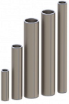
Piezoelectric tube scanners are thin cylinders of radially poled piezoelectric material with four external electrodes and a continuous internal electrode. When a voltage is applied to one of the external electrodes, the free end of the tube will bend towards the applied voltage. Vertical extension is achieved by applying an equal voltage to all external electrodes, or by applying voltage to the internal electrode.
Piezoelectric tube scanners are used extensively in scanning probe microscopes as XYZ nanopositioners, and other applications such as micro-manipulation, and beam scanning. The tubes can be ordered by themselves or with options including wiring and connectors for connection to a TD250-INV amplifier, and with mounting surfaces for easy assembly. Customized dimensions and/or electrode configurations are available on request.
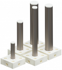
Piezoelectric tubes can be ordered individually, or in a complete assembly.
RoHS and REACH Compliance
Specifications:
| Order Code | Lgth | Dia. | Thk. |
Elctrd Clear | Max Volt | Scan RNG | Ext RNG | Res Freq | Quad Cap |
|---|---|---|---|---|---|---|---|---|---|
| (10) | (1) | (2) | (3) | (4) | (5) | (6) | (7) | (8) | (9) |
| mm | mm | mm | mm | Volt | µm | µm | kHz | nF | |
| TB1006-N | 10.0 | 6.0 | 0.65 | 0.7 | +/-260 | 3.2 | 2.1 | 31 | 3 |
| TB2006-N | 20.0 | 6.0 | 0.65 | 0.7 | +/-260 | 13 | 4.2 | 7.7 | 4 |
| TB3006-N | 30.0 | 6.0 | 0.65 | 0.7 | +/-260 | 29 | 6.3 | 3.4 | 6 |
| TB4006-N | 40.0 | 6.0 | 0.65 | 0.7 | +/-260 | 51 | 7.4 | 1.9 | 6 |
| TB5006-N | 50.0 | 6.0 | 0.65 | 0.7 | +/-260 | 80 | 11 | 1.2 | 10 |
| TB6006-N | 60.00 | 6.0 | 0.65 | 0.7 | +/-260 | 114 | 13 | .850 | 11 |
| TB10006-N | 100.0 | 6.0 | 0.65 | 0.7 | +/-260 | 318 | 21 | .310 | 19 |
NOTES:
- Length tolerance +/-0.2 mm
- Diameter tolerance +/-0.2 mm
- Thickness tolerance +/-0.1 mm
- Clearance between external electrodes, and between the electrodes and the ends of the tube. Tolerance +0.3 mm, -0.2 mm
- Maximum recommended bipolar voltage, between any external electrode and a grounded internal electrode.
- Peak-to-peak horizontal deflection with a fixed base and free end, when maximum voltages are applied to the X or Y electrodes and the internal electrode is grounded. Tolerance -20%, +30%.
- Peak-to-peak vertical deflection, when maximum voltages are applied to all external electrodes and the external electrode is grounded. Tolerance -20%, +30%.
- First bending mode resonance frequency with a fixed base and free end, see calculator below. Tolerance +/-20%.
- Capacitance between one external electrode and the internal electrode. Tolerance +/-30%
- Click part number to download a STEP file of the tube, including the mounting base and end-cap. Delete the mounting base and end-cap if not required.
Operating Principle
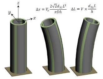
When the base of the tube is fixed, the tip translations Δx and Δy are approximately
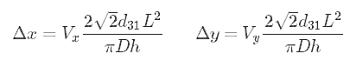
where Δx and Δy are the x and y axis deflection, d31 is the piezoelectric strain constant, L is the length of the tube, D is the outside diameter, h is the tube thickness, and Vx and Vy are the electrode voltages which are applied oppositely to either side of the tube.The tube deflects in the same direction as the positive electrode voltage.
The deflection can also be written as a function of the specifications, that is
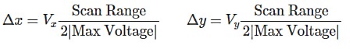
For example, the x axis deflection of the TB5509 is 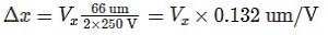
A positive voltage applied to all four quadrants will cause the tube to contract vertically and expand radially. The change in length is
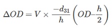
The change in outside diameter due to a positive voltage applied to all four quadrants is approximately
Driving Piezoelectric Tubes with the TD250 Amplifier
The TD250 is an ultra-low noise, six-channel 250V amplifier optimized for driving piezoelectric tube scanners. Although many configurations are possible, the driven internal electrode configuration shown below provides the maximum X, Y and Z travel range [1]. This configuration is also referred to as the “Full Length” configuration [1]. The performance of this method is compared to other configurations in reference [1].
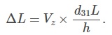
In the driven internal electrode configuration, the X and Y electrodes are driven in the standard way with equal and opposite voltages, as shown below. By applying a negative voltage to the internal electrode, a contraction equal to half the vertical scan range can be obtained. That is, the vertical deflection is 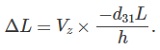
where Vz is a strictly negative voltage applied to the internal electrode.
This method exploits the higher positive electric field strength of the piezoelectric material, which is usually five times the negative electric field strength. Care must be taken not to apply positive voltages to the internal electrode since this can lead to depolarisation. For example, when using a non-inverting channel, the input is enforced to be negative as shown below. Alternatively, an inverting channel can be used and the input is enforced to be positive.
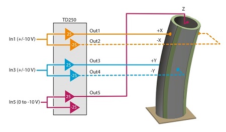
Wiring diagram of a piezoelectric tube driven by a TD250-INV amplifier. The X axis deflection is controlled by the In1 signal (+/-10V), which results in a non-inverted +/-250V signal at the +X electrode, and an inverted +/-250V signal at the -X electrode. A +10V signal applied to In1 results in maximum deflection toward the +X electrode, and a -10V signal results in maximum deflection toward the -X electrode (as pictured). The Y axis driving scheme is identical to the X axis. The vertical Z axis deflection is controlled by In5 (0V to -10V) which results in a negative voltage up to -250V on the internal electrode, and a contraction equal to half of the vertical travel range. When driving all three axes simultaneously, only half of the vertical travel range can be utilized.
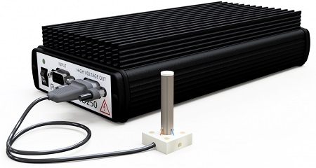
A tube assembly with base, top-cap, wiring, and connector. The TD250-INV amplifier is available separately.
Deflection and Resonance Frequency Calculator
The following calculator estimates the lateral and vertical travel range of a piezoelectric tube, with the conditions:
- The driven internal electrode configuration is assumed. That is, only negative voltages are applied to the internal electrode. If the tube is only used for elongation, the reported vertical travel range can be doubled.
- The “passive length” is an additional structure added to increase the travel range. This length is not included in the calculation of resonance frequency.
 Deflection and Resonance Frequency Calculator
Mounting
The most common mounting configuration is the cantilever arrangement with a fixed base and free end. The base can be bonded directly to an insulating surface with a general purpose two-part epoxy such as Loctite 3430. Piezoelectric Tubes can also be bonded to a conductive surface if >0.5mm clearance is maintained between high-voltage electrodes and the surface.
Electrodes
The tubes are supplied with a Nickel thin film electrode. The internal electrode is continuous and the external electrodes are quartered. Electrode area can be removed by etching with dilute Nitric Acid. Custom electrode configurations are available on request.
The electrode clearance specification is the length of external electrode removed from both ends, which provides electrical clearance to a mounting surface. The internal electrode is continuous.
In applications that require high magnetic fields, the Nickel electrodes can be replaced with Copper or Gold. Copper is an economical choice but Gold provides excellent corrosion resistance and electrical conductivity.
Electrical Current Requirements
Calculate Power Bandwidth
The required current is I=C dV/dt where I is the current, C is the effective capacitance, and dV/dt is the voltage rate of change. For a sine-wave, the required peak current is equal to: 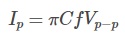 where Vp-p is the peak-to-peak voltage. For a triangle wave, the required peak current is equal to:
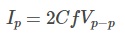
Assembly and mounting options
Piezodrive also sells end caps and mounting bases for our tube scanners. We also offer an assembly and wiring service.
Order Code
(Tube Order Code)-(Base)-(Top Cap)-(Bottom Cap)-(Assembled)-(Wiring)-(Connector)-L(Length)
- Tube Order Code: e.g. TB6006-N
- Base: Blank if no base or B
- Top Cap: Blank if no top cap or TC
- Bottom Cap: Blank if no top cap or BC. Not available with base
- Assembled: Blank if not assembled (glued) or A, only available with B, TC, or BC
- Wiring: Blank if no wiring. W if tube wiring only available with assembly. V for vertical wiring, not available with base. H for horizontal wiring, not available with base.
- Connector: Blank for unterminated wires or DSUB. Only available with wiring option selected.
- Length: Length of the wiring in meters. Only available with wiring option selected.
Example 1
A TB3507 assembled in a base with a top cap and 1 meter D-Sub cable:
TB3507-B-TC-A-W-DSUB-L1
Example 2
A TB6006 with 1 meter of unterminated vertical wiring:
TB6006-V-L1
Example 3
A TB2005 with a base and top cap but no assembly or wiring:
TB2005-B-TC
Wiring Service
Piezoelectric tubes can be supplied with wires attached to all external and internal electrodes. The standard options and order code suffixes are:
| Order Suffix | Description |
|---|---|
| -W10V | 10cm AWG30 wires soldered near the base traveling vertically downward |
| -WxxV | AWG30 wires soldered near the base traveling vertically downward, where xx is the length in cm |
| -W10H | 10cm AWG30 wires soldered near the base traveling horizontally |
| -WxxH | AWG30 wires soldered near the base traveling horizontally, where xx is the length in cm |
Soldering Instructions
Wires can be attached using conductive epoxy (Circuitworks CW2400) or solder and Rosin flux.
Conductive epoxy has the advantages of being flexible and avoids the requirement for heat so there is no risk of thermal depolarization; however, it is time consuming to apply and requires some care to avoid short-circuits due to spillage. Epoxy is recommended for applications that involve continuous operation with full-range cycling of deflection.
Soldering is quicker and easier than conductive epoxy but requires some care to avoid overheating the tube. The required materials and tools include:
- Gloves, safety goggles
- Piezotube with Nickel electrodes
- Insulated wire, e.g. AWG30 Kynar insulated wire
- Superior Flux 67, or rosin flux, e.g. Chemtronics CW8200
- Cotton buds
- 60/40 Sn/Pb 0.5mm Solder wire, e.g. Multicore 3096525-M
- Temperature controlled soldering iron
- Isopropanol or Acetone
The recommended steps are:
- Strip the end of the wire by 3-5 mm, then tin the wire with solder. Finally, trim the tinned wire to 2mm.
- Apply a small amount of flux to the desired soldering point by wetting a cotton bud with flux and wiping a 2mm diameter area on the tube. Wetting a larger area is ok but this tends to result in a larger solder joint.
- Set the soldering iron temperature to 300C, and preferably check with a temperature sensor.
- Deposit a 2mm diameter spot of solder on the tube using a brief contact of the hot tip and solder.
- Attach the tinned wire to the solder spot using a brief contact.
- Clean off the flux with isopropanol or acetone. An isopropanol bath is recommended for 10 minutes to assist with removing all residues.
- Handling the tube with gloves will avoid finger marks on the tube.
Vacuum Compatibility
Piezoelectric tubes do not contain any outgassing materials and are fully vacuum compatible.
Cryogenic Compatibility
The material PZT-5H works well at cryogenic temperatures. As a guide, the displacement sensitivity is reduced by a factor of 5. However, at cryogenic temperatures, the applied voltage can be increased from +/-250 V to +/-1000 V, which can regain the majority of room temperature deflection but requires a high voltage.
For example, the predicted deflection of the TB5509 tube is 66 µm with an applied voltage of +/-250 V. At cryogenic temperatures, the displacement will reduce to 66 μm x 0.2 = 13.2 μm .
However, if the voltage is increased to +/-500 V, the deflection will be approximately 66μm x 0.2 x 500/250 = 26.4 μm .
If the voltage is increased to +/-1000 V, the displacement will be approximately 66 μm x 0.2 x 1000/250 = 52.8 μm
Options/OEM Customization
- Custom dimensions and thickness
- Custom electrode configurations
- Custom wiring arrangements / connectors
- Mounting platform design and fabrication
Piezoelectric Properties
The piezoelectric material is similar to PZT-5H and Navy Type VI.
| Property | Symbol | Value | Unit |
|---|---|---|---|
| Piezoelectric constants | d33 | 600 | 10-12m/V |
| d31 | -270 | 10-12m/V | |
| g33 | 19.4 | 10-3Vm/N | |
| g31 | -9.2 | 10-3Vm/N | |
|
Electro-mechanical coupling coefficients |
Kp | 0.65 | NA |
| Kt | 0.37 | NA | |
| K31 | 0.38 | NA | |
| Frequency constant | Np | 1980 | Hz-m |
| Nt | 1950 | Hz-m | |
| N31 | 1450 | Hz-m | |
| Elastic constant | Y33 | 5.3 | 1010N/m2 |
| Y11 | 7.2 | 1010N/m2 | |
| Q Factor | Qm | 80 | NA |
| Dielectric constant | e33/e0 | 3500 | @1 kHz |
| Dissipation fator | tan δ | 2.5 | % @1 kHz |
| Curie Temperature | Tc | 220 | C |
| Density | ρ | 7.8 | g/cm3 |