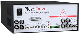
PD200X4 - Four Channel Power Amplifier
Piezoelectric Drivers
 PD200X4 Users Manual
 Calculate Power Bandwidth
Electrical Specifications:
| Electrical Specifications | |||
|---|---|---|---|
| Output Voltage Ranges | 100 Vp-p | 150 Vp-p | 200 Vp-p |
| RMS Current | 1.2 Amps | 0.91 Amps | 0.57 Amps |
| Peak Current | 2.0 Amps | 2.0 Amps | 2.0 Amps |
| Pulse Current | 10.0 Amps | 10.0 Amps | 10.0 Amps |
| Power Bandwidth | 470 kHz | 310 kHz | 230 kHz |
| Gain | 20 V/V | ||
| Slew Rate | 150 V/us | ||
| Signal Bandwidth | 680 kHz | ||
| Load | Any | ||
| Noise | 714 uV RMS (10 uF Load, 0.03 Hz to 1 MHz) | ||
| Protection | Continuous short-circuit, thermal | ||
| Voltage Monitor | 1/20 V/V | ||
| Current Monitor | 1 V/A | ||
| Analog Input | +/-10V, Zin = 100k, protected up to +/-20V | ||
| Output Connectors | BNC, Screw Terminals, LEMO 0B | ||
| Power Supply | 90 Vac to 250 Vac | ||
| Mechanical Specifications | |||
|---|---|---|---|
| Environment | 0 - 40 C (32-104 F), Non-condensing humidity | ||
| Dimensions | 212 x 304.8 x 88 mm (8.35 x12 x 3.46 in) | ||
| Weight | 2kg (4.4 lb) | ||
Features
The PD200X4 is a four-channel linear amplifier for driving piezoelectric actuators and other loads. The output voltage range can be unipolar, bipolar, or asymmetric from 50V to 200V. Up to +/-200V can be achieved using two channels with a bridged load. Refer to the specifications table for the available output voltage ranges. Front panel switches and dedicated connectors for independent and bridged loads make it easy to switch between four independent channels and two bridged channels with double the voltage range.
The PD200X4 can drive any load impedance including unlimited capacitive loads such as stack actuators; standard piezoelectric actuators; two wire benders; and three-wire piezoelectric benders requiring a bias voltage. Bias voltages can be generated using two auxiliary outputs linked to the power supply voltages, or by using an amplifier channel with a constant DC offset.
A range of user controls and ordering options are available to provide maximum application flexibility. The DC offset of each channel can be controlled by a front panel potentiometer, or can be fixed to zero as an option. The maximum positive and negative output voltages can be restricted using two front panel potentiometers. A 15-pin DSUB connector on the front panel includes signals for inputs, voltage monitors, current monitors, temperature measurement, a digital status output, and a digital shutdown input.
The output connectors include BNC for independent channels, LEMO 0B for bridged channels, and a plug-in screw terminal. The PD200X4 is suited to a wide range of applications including electro-optics, ultrasonics, vibration control, nanopositioning systems, and piezoelectric motors.
| Compatible Actuators | |
|---|---|
| Stack Actuators | 50V to 200V (4 Channels) |
| Plates and Tubes | +/-100V or +200V with a grounded load (4 Channels)+/-200V with a bridged load (2 Channels) |
| Two Wire Benders | +/-100V or +200V with a grounded load (4 Channels)+/-200V with a bridged load (2 Channels) |
| Three Wire Benders | Up to +200V with +200V bias (4 Channels + Bias source)+/-100V with +/-100V bias (4 Channels + 2 Bias sources) |
Output Voltage Range
The output voltage range is specified when ordering. The standard voltage ranges and associated current limits are listed below, further options can be found in Section 18 of the product manual. The PD200X4 has front panel controls for reducing the positive and negative output voltage range, so a voltage equal to, or slightly greater than the required voltage is recommended.
| Negative Voltage | Positive Voltage | Bridge Mode | RMS Current | Peak Current | Order Code |
|---|---|---|---|---|---|
| 0V | +200V | ±200V | 0.57A | 2A | PD200X4-P200 |
| 0V | +150V | ±150V | 0.91A | 2A | PD200X4-P150 |
| 0V | +100V | ±100V | 1.20A | 2A | PD200X4-P100 |
| -25V | +125V | ±150V | 0.91A | 2A | PD200X4-N25-P125 |
| -25V | +75V | ±100V | 1.20A | 2A | PD200X4-N25-P75 |
| -50V | +150V | ±200V | 0.57A | 2A | PD200X4-N50-P150 |
| -50V | +100V | ±150V | 0.91A | 2A | PD200X4-N50-P100 |
| -50V | +50V | ±100V | 1.20A | 2A | PD200X4-N50-P50 |
| -75V | +75V | ±150V | 0.91A | 2A | PD200X4-N75-P75 |
| -75V | +25V | ±100V | 1.20A | 2A | PD200X4-N75-P25 |
| -100V | +100V | ±200V | 0.57A | 2A | PD200X4-N100-P100 |
| -100V | +50V | ±150V | 0.91A | 2A | PD200X4-N100-P50 |
Power Bandwidth
The ‘power bandwidth’ is the maximum frequency at full output voltage. When the amplifier output is open-circuit, the power bandwidth is limited by the slew-rate; however, with a capacitive load, the maximum frequency is limited by the RMS current and load capacitance. The power bandwidth can be determined using the calculator below. Click to open.
Calculate Power Bandwidth
Delivery Contents
- PD200X4 amplifier with plug-in screw terminal installed
- IEC C13 power cable, suited to the shipping destination
Warranty
PiezoDrive amplifiers are guaranteed for 12 months from the date of delivery. The warranty does not cover damage due to misuse.